


As noted elsewhere on the Rothos Energy Systems GmbH website, industrial process heat systems use a range of heat transfer media. Further information is available in the technical article Optimize your heat transfer system instead of replacing it.
In the European Union, a thermal oil heater installation comprising the heater, auxiliary equipment and piping may fall within the scope of the Pressure Equipment Directive (2014/68/EU) and, in Germany, the Industrial Safety Regulation (BetrSichV). Depending on the design and operating conditions, notification, authorisation and inspection obligations may apply. The applicable requirements and the qualifications needed to carry out inspections must be assessed for each individual installation.
The EU directive applies within the European Union, while the German Industrial Safety Regulation applies in Germany. Installations in other countries are subject to the relevant national requirements.
Thermal oil analysis: standards and procedures
This technical article focuses specifically on thermal oil analysis. It can play an important role in ensuring the safe and reliable operation of thermal oil heater systems. The applicable inspection requirements and intervals depend on the installation and the relevant rules.
The types of analysis and the heat transfer fluids to be tested are described in DIN 51529, “Testing and assessment of used heat transfer fluids”.
Depending on the installation and the inspection task, different qualification requirements may apply to the people or organisations involved. Analyses are generally carried out by thermal oil suppliers or chemical laboratories.
The thermal oil manufacturer or supplier specifies the permissible limits for the thermal oil in use.
Which parameters are checked in a thermal oil analysis?
For mineral-based organic thermal oils, the following parameters are determined:
- Kinematic viscosity
- Closed-cup flash point
- Neutralisation number (acid number)
- Carbon residue
- Water content (optional parameter)
An assessment is made by comparing the permissible limits with the measured analysis results.
Example: analysis results
| Parameter | Thermal oil analysis result | Fresh-oil value | Assessment |
| Viscosity | 51.32 mm²/s | 31.0 mm²/s | The value has increased compared with previous analyses. The original assessment attributes this change to the addition of 20,000 litres of fresh thermal oil in September 2012. |
| Flash point | 136 °C | 220 °C | Taking the age and thermal exposure of the oil into account, the original assessment considers the flash point to be within the usual range and the current value acceptable. |
| Conradson carbon residue | 0.12 wt.% | 0.0 wt.% | At 0.12 wt.%, the Conradson carbon residue is above the stated fresh-oil value of 0.0 wt.%. |
| Solid contaminants | Not analysed | 0.0 wt.% | Annual thermal oil filtration is recommended. This can be achieved by installing a side-stream filtration system that operates while the plant is running. |
| Neutralisation number | 0.06 mg KOH/g | 0.0 mg KOH/g | The neutralisation number is slightly above the fresh-oil value but remains well below the permissible limit. |
| Water content | <100 ppm | <100 ppm | With less than 100 ppm of water, the sample is assessed as being in a very good range. |
For mineral-based organic heat transfer fluids, it may also be useful to determine the low-boiling and high-boiling fractions.
Synthetic thermal oils
For synthetic thermal oils, the following parameters are checked:
- Kinematic viscosity
- Closed-cup flash point
- Neutralisation number (acid number)
- Conradson carbon residue
- Water content
- Non-volatile residues
- Low-boiling and high-boiling fractions
As with mineral-based organic thermal oils, evaluating these parameters provides information that can be used to assess the condition of synthetic thermal oils.
General note: If a mineral-based organic thermal oil has lost the necessary physical and thermal properties, it may no longer be suitable for continued use and must then be disposed of as waste oil if it cannot be treated to an acceptable condition. Certain synthetic thermal oils can be reprocessed by their manufacturers and returned to service.
Why carry out thermal oil analyses?
Thermal oil heater systems are designed on the basis of the properties of fresh thermal oil. Exposure to high temperatures can alter the molecular structure of thermal oil, a process referred to as ageing.
Ageing changes the oil’s chemical and physical properties. This can impair heat transfer and increase energy consumption. Changes in the vapour pressure and the composition of volatile fractions can also lead to evaporation phenomena and operational problems. Under certain conditions, safe operation may be affected. Suitability for applications with specific water-hazard or food-related requirements may also need to be reassessed.
Which limits must be observed?
DIN 51529 specifies the parameters to be analysed. The thermal oil manufacturer or supplier provides the relevant permissible limits.
Does thermal oil have to be replaced when a value falls outside its permitted limits?
Not necessarily. Replacement becomes necessary if suitable treatment measures cannot restore the oil to an acceptable condition.
Note: Thermal oil suppliers often recommend replacement as soon as a measured value falls outside the permissible range. Potential treatment options, such as those described below, may not always form part of the supplier’s recommendation.
How can the condition of aged thermal oil be improved?
1. Partial replacement of thermal oil
Partial replacement may improve the measured oil parameters only for a relatively short period. Fresh oil can soon be affected by the condition of the remaining oil.
Partial replacement requires a production shutdown. In addition, solid particles may not be adequately removed.
2. Thermal oil filtration
Thermal oil filtration is appropriate when analyses reveal elevated concentrations of solid particles or coking residues.
For larger installations with a thermal oil volume of around 10,000–20,000 litres or more, mechanical cleaning can be performed using filter stations with filter housings and a dedicated pump. Provision for such a station should ideally be included when planning a new installation. The thermal oil system does not have to be shut down for this procedure.
For smaller installations, mechanical cleaning may be achieved with a switchable dual-strainer filtration station. In this case, too, filtration can take place without shutting down the system.
3. Thermal oil boil-out treatment
Thermal oil boil-out treatment can have a positive effect on parameters such as viscosity, flash point, neutralisation number and the high-boiling fraction.
The Rothos Energy Systems GmbH boil-out system is integrated into the thermal oil installation. It can be installed at comparatively low cost and can achieve significant improvements. Compared with more complex systems requiring a separate circulating pump, condensate cooler and controls, it is substantially less expensive to implement.
How the Rothos boil-out system works
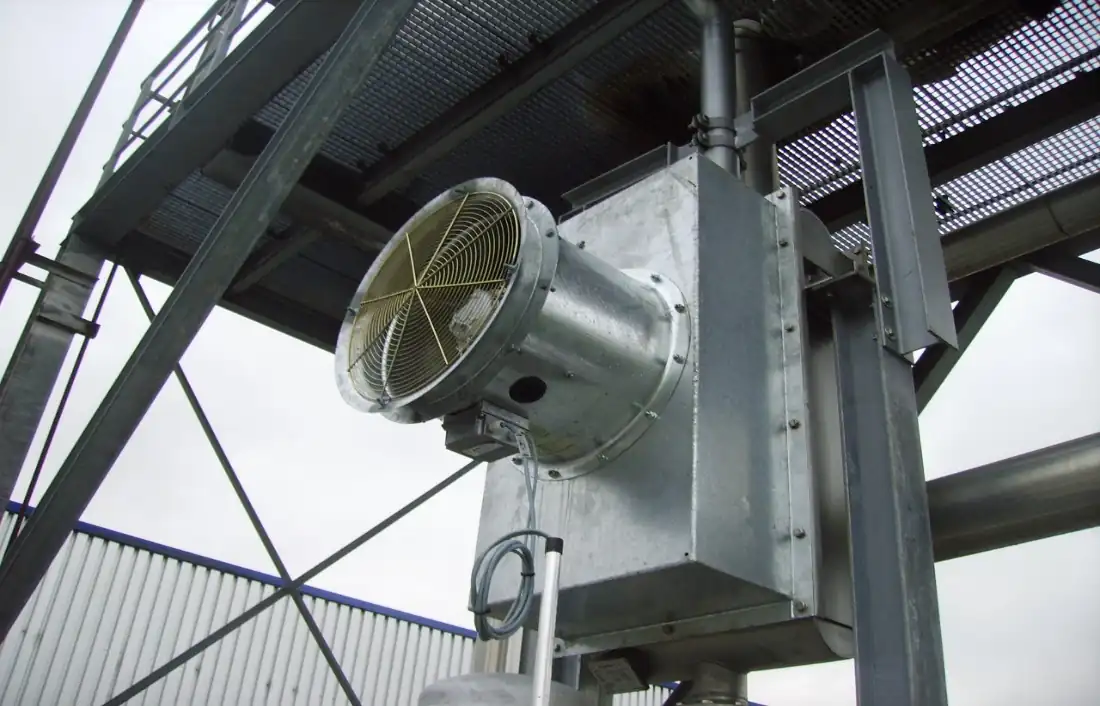
During normal operation of the thermal oil system, a small portion of the primary-circuit flow is directed through a dedicated hot-oil transfer line to the expansion vessel. The thermal oil is heated to approximately 260 °C.
During the boil-out process, the expansion vessel is connected to the collection vessel via an overflow line and to the atmosphere via a vent line. A nitrogen sparging lance is installed at the bottom of the expansion vessel. It introduces nitrogen into the hot thermal oil as fine bubbles.
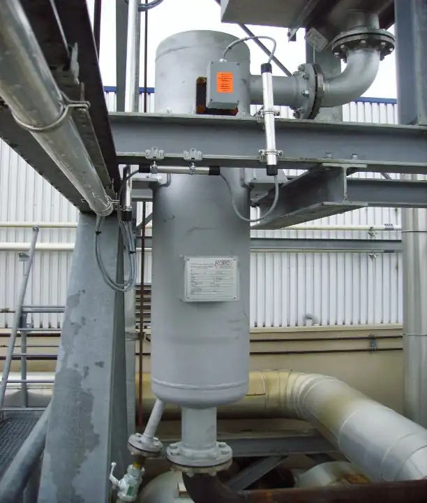
At the surface of the hot thermal oil in the expansion vessel, volatile low-boiling components are released as vapour. The nitrogen carries these components into the overflow line. To prevent the vapours from entering the collection vessel or being discharged directly into the atmosphere, a condensation vessel is installed in the overflow line.
The low-boiling components condense on the available cooling surface in this vessel and collect at the bottom. A level monitor indicates the fill level. The condensate must be drained to prevent liquid from entering the collection vessel. The nitrogen carrier gas is discharged through the vent line to the atmosphere.
This boil-out system can be used while production continues. It may be necessary to top up the thermal oil system with small amounts of fresh thermal oil.
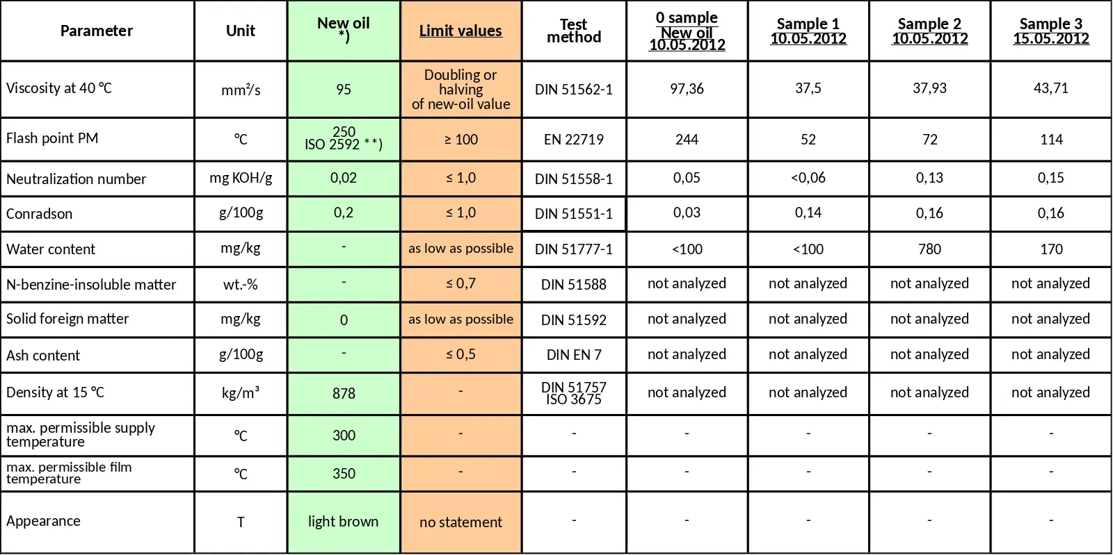
Comparison of thermal oil analyses
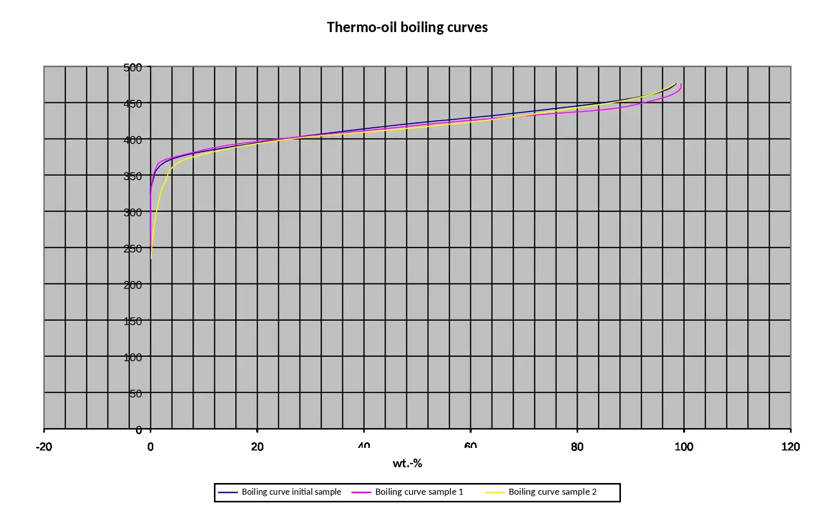
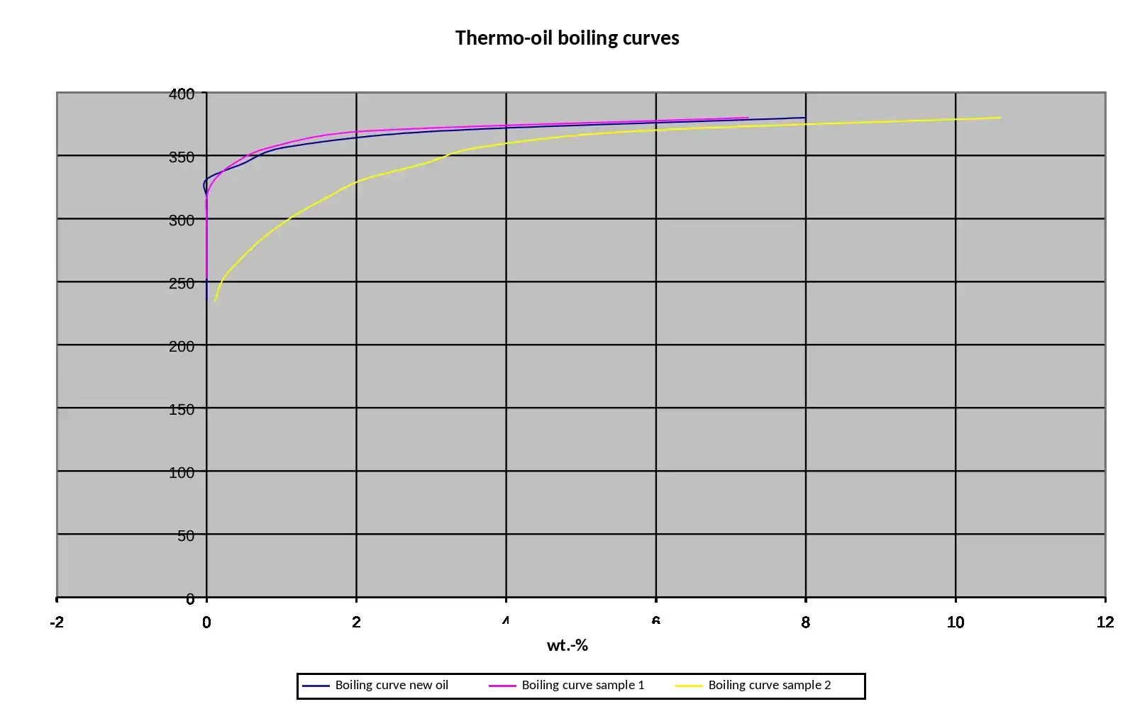
4. Boiling-range curves
The boiling-range curves allow the initial reference sample (sample 0) or fresh oil to be compared with later thermal oil samples.
5. How are thermal oil samples taken?
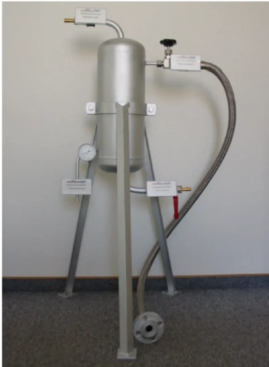
A sample must be taken from the primary supply line through a suitable shut-off valve and a sample cooler. The thermal oil must be cooled to a maximum of approximately 50 °C before being collected in two 1-litre metal sample bottles, which must then be sealed airtight immediately.
For new installations, a sampling point with a cooler should be included during the design stage. An initial reference sample (sample 0) should always be taken when a new installation is commissioned or the system is refilled.
A suitably trained competent person should be familiar with the sampling procedure.
6. Conclusion
Before deciding to replace the thermal oil, operators should consider consulting Rothos Energy Systems GmbH.
The measures we have recommended have helped many companies continue operating their thermal oil systems with oil that meets the permissible limits.
In many cases, this has prevented or postponed production shutdowns. In some cases, companies have also avoided significant costs for refilling their thermal oil systems, allowing major expenditure to be postponed for years.
Rothos Energy Systems GmbH can advise on the technical options available for industrial heat transfer systems.
Would you like to have an existing heat transfer system assessed? Contact Rothos Energy Systems.